Triangulation
What is Triangulation method in surveying? The object of geodetic survey is to determine the relative or absolute positions of points the surface of the earth varies precisely. The relative positions are determined in terms of lengths and azimuths of lines joining them. The absolute positions are determined in terms of latitude, longitude and elevations above the mean sea level. However, the distinctions between plane surveying and geodetic surveying is fundamentally of extent area rather than operations.
The precise method of geodesy are followed in the field work of excessive plane trigonometrical survey also. Since the area embraced area by geodetic survey for an appreciable position of the earth surface, the sphericity of the earth is taken into account while making the computations. The geodetic points so determined furnish the most precise control to which a more detailed survey of the intervening country may be referred.
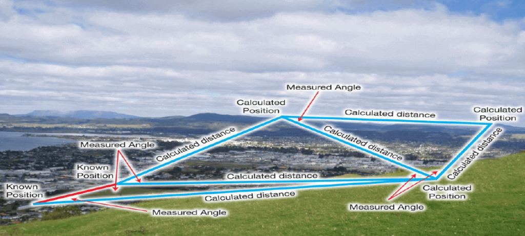
In triangulation survey, the system consists of a number of interconnected triangles in which the length of only one line called the base line and angles of the triangles are measured very accurately. Knowing the length of one side and the three angles, the length of the other two sides of the triangles can be competed. The verticles or apexes of the triangles are known as triangulation stations and the whole figure is called triangulation figure or triangulation system.
The defect of triangulation method in surveying is that it tends to accumulate the errors of length and azimuth, as the length and azimuth of each line are dependent on the length azimuth of the preceding line. To control the accumulation or error, subsidiary bases are also selected. These stations are called Laplace station.
Purpose for conducting triangulation
Triangulation method in surveying is conducted for one or more of the following purposes:
- To establish accurate control points for plane and geodetic survey of large areas.
- To establish accurate ground control points for photogrammetric survey of large areas.
- To determine the size and shape of the earth by making observations for latitude, longitude and gravity.
- For various engineering projects it is required to build up accurate horizontal control.
Types of triangulation survey
The triangulation survey systems are classified according to the accuracy required for horizontal controls. It depends on the type of survey, extent of survey and purpose of survey. On the basis of accuracy and purpose the triangulation survey systems are classified as follows:
1. Primary or First Order Triangulation Systems:
This system of triangulation survey is of the highest grade. It provides the framework for the national control network for subsidiary triangulation stations. Primary triangulation survey is generally conducted for determination of the shape and size of the earth, for earth’s crustal movement studies in areas of seismic activities for engineering projects of high precision and for surveys conducted in metropolitan areas.
2. Secondary or Second Order Triangulation Systems:
This system of triangulation survey is of the grade slightly lower than that of the primary triangulation survey system. Generally, a secondary triangulation survey system is provided within a primary triangulation system. It provides Control points closer than those of the primary triangulation survey system. The secondary triangulation systems are connected to the primary triangulation stations at various points. These are used for detailed surveys in areas where great accuracy is not required. It is used to establish control for interstate and inland subdivisions.
3. Tertiary or Third Order Triangulation Systems:
This system of triangulation survey is of the grade lower than that of the secondary triangulation system. It is used to provide control points between stations of primary and secondary triangulation systems. Tertiary triangulation systems are used to establish control for local development, topographic surveys, heightographic surveys and other such projects where lower accuracy can be accepted. It is also known as topo triangulation, as it is normally used for providing control in topographic surveys.
Triangulation Figures
A triangulation figure or triangulation system is a group of system of triangles such that any triangle has one side, and only one side common to each of the preceding and the following triangles. The commonly used triangulation figures are as follows:
1. Single Chain of Triangles
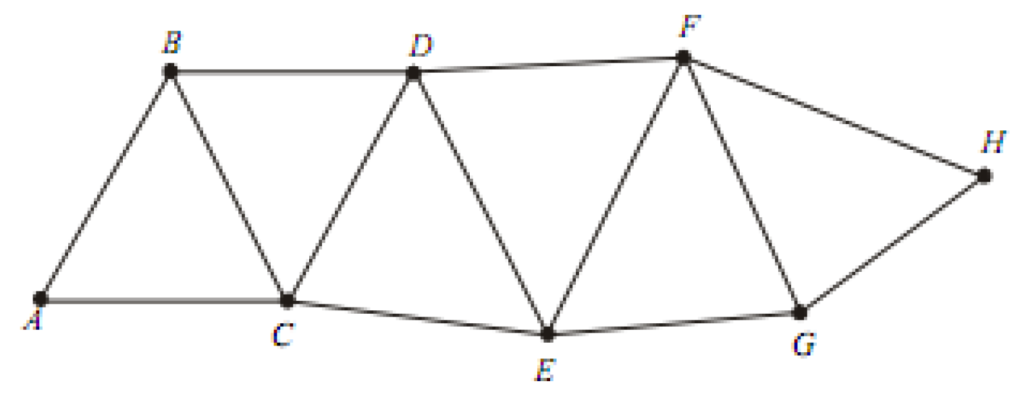
This triangle is used when a narrow strip of land is to be covered. Though the system is rapid and economical, it is not so accurate for primary triangulation works as the number of conditions to be fulfilled in the figure adjustment is relatively small also it is not possible to carry out the solution of the triangles through the figures by independent routes. If the accumulation of error is not to become excessive, base lines must be introduced frequently.
2. Double Chain of Triangles
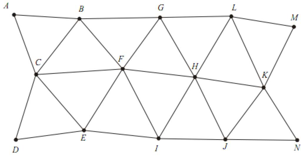
The double chain of triangles is used to cover a broader area.
3. Centered Triangles and Polygons
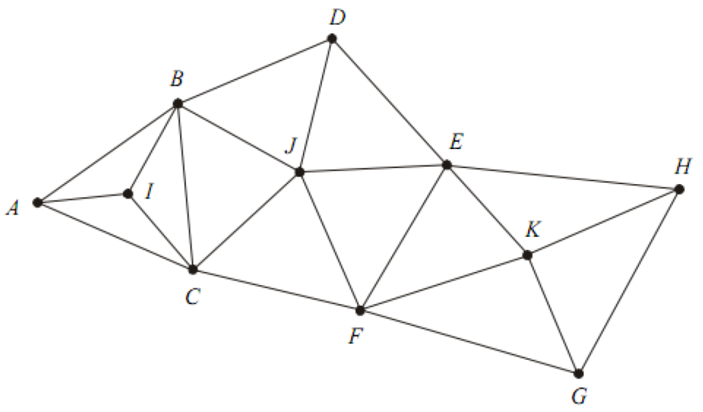
In this arrangement there is always an interior station. The interior station may be bounced by three or more sides. The interior station is a common vertex for all the triangles. This arrangement provides the required checks on computations. However, the progress of work is slow due to more number of instrument stations.
4. Braced Quadrilaterals
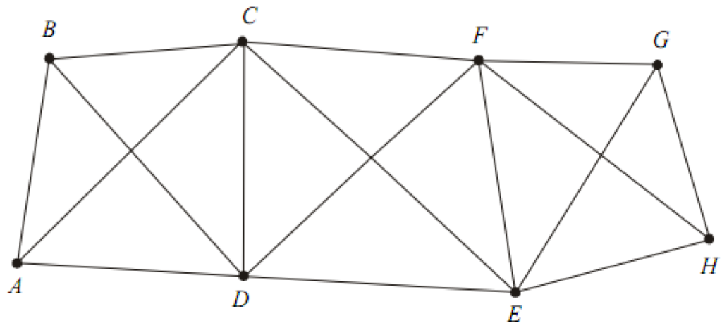
Quadrilaterals with four corner stations and observed diagonals form the best triangulation figures. These are best suited for hilly terrains. Since the computed length of sides can be carried through the system by different combination of sides and angles, this system is the most accurate among all the system.
Criteria for Selection of Triangulation Figures
The following are the factors to be considered while selecting a particular triangulation figure:
1. The figure should be such that at least one and preferably both the routes should be well conditioned.
2. The figure should be such that the computations can be done through two dependent routes.
3. The length of all the lines in a figure should be comparable. Very long or very short lines should be avoided.
4. The figure ought to be to such an extent that least work might get most extreme advancement.
Framework of Primary Triangulation System in a Country
The following two types of framework of primary triangulation system are used for a country to cover the entire area:
1. Grid-Iron System
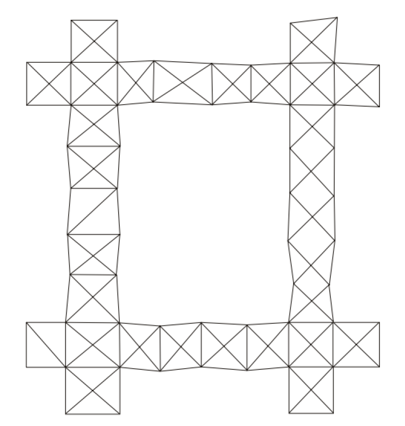
In this framework, the primary triangulation system consists of a series of change of braced quadrilaterals, generally East-West and North-South. The distance between two chains vary from 150 km to 250 km. The area between the parallel and perpendicular series of change of primary triangulation systems are covered by secondary and tertiary triangulation systems.
2. Central System
In this framework, the entire region is covered by an organization of primary triangulation framework, reaching out all the way of frameworks from underlying figure, which is laid by and large at the focal point of the country.
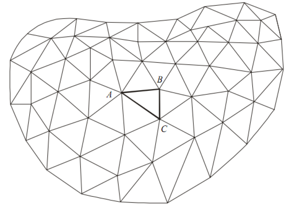
Well-Conditioned Triangle
A triangle is called well conditioned if its shape is such that any error in the measurement of an angle has minimum effect on the computed lands. The triangles used in a triangulation system should be well conditioned. The accuracy achieved in a triangulation method in surveying depends on the shape of the triangles.
In any triangle of a triangulation system, the length of one of its size is known. It is either measured in the field or more frequently obtained from the computations of the adjacent preceding triangle. The error in the computation of the other two sides will effect the rest of the triangles. To ensure that the two computed sides are equally effected, the triangle should be isosceles.
For more engineering terms click here.